Electromagnetic compatibility (EMC) is one of the most challenging aspects of integrating rugged computers into defence platforms. A system that passes all environmental tests but fails MIL-STD-461 creates serious programme delays. Understanding the standard — and how to work with your supplier — can prevent costly late-stage surprises.
What MIL-STD-461 Covers
MIL-STD-461 (Requirements for the Control of Electromagnetic Interference Characteristics of Subsystems and Equipment) defines requirements and test procedures for electromagnetic emissions and susceptibility. It applies to equipment and subsystems installed on military platforms — aircraft, ships, ground vehicles, space systems and fixed installations. The current revision is MIL-STD-461G (2015). Emission limits and susceptibility thresholds vary depending on the installation (above or below deck, external platform, etc.).
Key Test Methods — Emissions
- ›CE101: Conducted emissions, power leads, 30 Hz – 10 kHz. Measures low-frequency noise injected back into vehicle/aircraft power bus.
- ›CE102: Conducted emissions, power leads, 10 kHz – 10 MHz. Higher frequency conducted noise on power inputs.
- ›RE101: Radiated emissions, magnetic field, 30 Hz – 100 kHz. Magnetic field radiation from equipment — important for magnetic compass interference.
- ›RE102: Radiated emissions, electric field, 10 kHz – 18 GHz. The primary radiated emission test — measures broadband RF emissions from the equipment chassis and cables.
Key Test Methods — Susceptibility
- ›CS101: Conducted susceptibility, power leads, 30 Hz – 150 kHz. Tests immunity to low-frequency power bus disturbances.
- ›CS114: Conducted susceptibility, bulk current injection, 10 kHz – 400 MHz. A key test for immunity to RF currents induced on cables.
- ›CS115: Conducted susceptibility, bulk current injection, impulse. Transient immunity on signal and power cables.
- ›CS116: Conducted susceptibility, damped sinusoidal transients. Simulates switching transients on power and signal lines.
- ›RS103: Radiated susceptibility, electric field, 2 MHz – 40 GHz. Tests immunity to external RF fields — radar, communications, jamming.
Design Practices for MIL-STD-461 Compliance
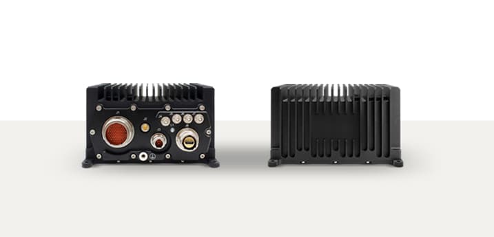
- ›Chassis shielding: Fully metal, conductive chassis with gasket-sealed seams significantly reduce RE102 radiated emissions. Avoid plastic panels or poorly bonded covers.
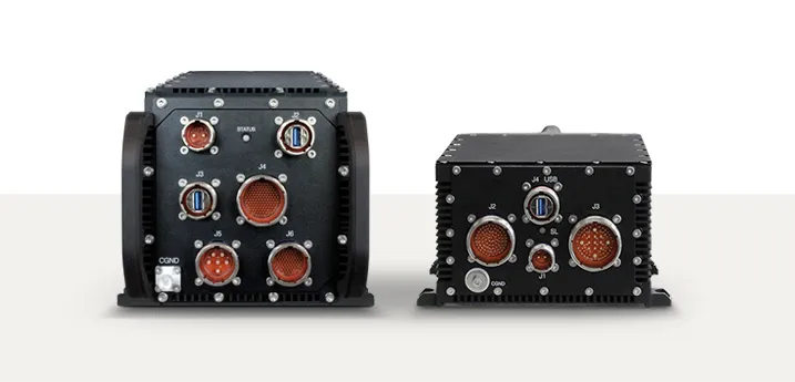
- ›Cable shielding and termination: All I/O cables should use shielded conductors with 360° shield termination at the chassis connector — not pigtail grounds.
- ›Filtered power inputs: EMI filter modules on DC power inputs suppress CE101/CE102 conducted emissions. Specify MIL-grade EMI filters with appropriate attenuation.
- ›PCB layout: Careful ground plane design, decoupling capacitor placement and clock signal routing reduce internal noise generation that drives emissions.
- ›Connector selection: MIL-DTL-38999 circular connectors with conductive backshells are preferred for MIL-STD-461 installations — they provide continuous shield termination.
Working with Your Rugged Computer Supplier
- ›Request existing MIL-STD-461G test reports and review which tests were conducted and at what installation category.
- ›Clarify which installation category your platform falls under (Army-ground, Navy-surface ship, Air Force-aircraft) — limits differ.
- ›Ask whether the test was performed on the standalone unit or as part of a cable harness — cable configuration significantly affects results.
- ›Identify any test waivers or open findings in the supplier’s existing test reports.
- ›Discuss cable and connector requirements early — late changes to connector types or cable routing can invalidate existing compliance evidence.